SHEAR STRENGTH
TO BE CONTINUED & EDITED SHORTLY
The following methods are
used for measuring the shear strength, of soil:-
(1) Direct shear test.
(2) Unconfined
compression test.
3 Triaxial
test.
(4) Vane shear test.
Direct shear and triaxial tests are used both for cohesive
and co- hesionless soils where as the unconfined compression test is employed
only for cohesive soils because cohesionless soils are not able to form an
unsupported soil cylinder. Vane shear test is also useful for cohesive soils of
low shear strength. The details of all the above tests, to be performed for
measuring the shear strength of soil, are described below.
SHOWING SECTIONAL DETAILS OF THE MACHINE
1. Direct shear test: This test is usually carried out in a
box and as such is known as shear box test. It consists of the following
parts:- These terms indicate the respective speeds at which undrained and
drained shear tests are usually conducted.
(1) A box of brass or gun metal, square or circular in cross
section, open at the top and bottom. The box is split up horizontally into two
equal halves which can be accurately fixed together. The di- mensions of the
sample of soils ranging from clays to coarse sands are 6 cm x 6 cm x 2 cm and
for gravels are 30 cm x 30 cm x 15 cm.
(ii The lower portion which is rigidly held in position in a
container.
(iii) A geared jack for pushing forward the container at a
constant rate:
(iv) Loading yoke.
(v) Steel ball.
(vi) Pressure pad.
(vii) Vertical deformation dial gauge.
(viii) Water grooves.
(ix) Porous plates.
Preparation of specimens
If the strength of the cohesive soil is required in its
natural state, then, every effort should be made to obtain undisturbed
specimens. If undisturbed specimens are unobtainable, then, remoulded specimens
should be used and an approximate correction must be made for the loss in
strength due to remolding. When the soil is to be disturbed and compacted, as
in the case of earthen dams, embankments etc; the strength should be determined
from remoulded specimens. In case of gravels and sands (i.e. cohesion less
soils), there is usually no objection to remoulding provided the natural
density and moisture content are known.
If the soil is cohesive, it should be compacted uniformly to
the required moisture content and dry density. After this, the specimen should
be trimmed to the required dimensions.
Procedure: The following procedure is adopted :-
(i) First of all place the porous plate at the bottom in the
shear box
(ii) Place the soil sample over it and, then, over the
sample place an- other porous plate. In case the soil is hen, before placing
cohesionless, then, the porous plate the surface of the soil should be levelled
with the help of a leveler shown in fig.
(iii) Assemble the shear box parts and place it in its
proper position.
(iv) Place the loading cap on the soil sample.
(v) Fix the vertical deformation measuring dial and note
down its initial reading.
(vi) Apply some initial load on the sample and note the
defor- mation readings at intervals of 5, 15, 30 seconds 1, 2, 4, 8, 15, 30 60
mts and 2, 4, 8, 16, 24 hours. Increase the loading till the desired normal
load is achieved under which the sample is required to be sheared.
(vii) Now adjust the horizontal measuring dial guage and
note down its initial reading.
(viii) Apply the shear load. The rate of shear must not
increase 0.01 mm per minute for cohesive soils.
(ix) Now apply a very small load on the shear box by
starting the motor of the machine.
(x) After this, remove the screws which hold the two portions
of the shear box so that the portions of the shear box do not have any
connection except the soil sample placed in the box.
(xi) Adjust the dial gauge measuring vertical deformations
inorder to measure the expansions or contractions.
(xii) Note down the initial readings on all the dial gauges.
(xiii) Now start applying the horizontal force and record
the readings for shear force, time, shear and normal displacement. Record the
readings initially after 5 mts.
(xiv) Continue the shearing of the soil sample till a
constant load is maintained.
Calculations:
(i) Maximum shear stress= maximum shearing force area of
soil sample
(i) Normal pressure total normal load area of soil sample
(iii) Maximum angle of internal friction
i. e., $=tan-1( maximum shear stress normal pressure )
(iv) Plot the graph between normal load and shearing force.
From the graph, get the value of 'c' (cohesion) as the interception on the
axis-Y and angle of internal friction as the slope of the curve
(v) Plot the following relation also :-
(a) Shear stress versus normal stress.
(b) Vertical displacement versus lateral displacement.
Precautions: The following precautions must be considered while
performing the experiment :-
(i) The inner dimensions of the box should be measured care-
fully before placing the soil sample in it.
(ii) The top surface of the soil should be levelled before
placing porous plate over it.
(iii) The soil should be air dried and not oven dried
because by oven drying the sample, the angle of internal friction changes.
✔Practical utility: The
practical utility of a direct shear test is to evaluate;
(i) maximum shearing resistance of soil;
(ii) bond resistance (it affects the displacements and
settlements of the superimposed structure and hence its safety);
(iii) temporary or permanent decrease in strength after
failure;
(iv) stress-strain and volume characteristics which are
helpful in finding out critical void ratio of cohesionless soils.
Form the above information, we can find out the suitability
of soil for maintaining the stability of retaining walls, braced excavations,
embankments etc.
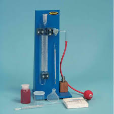
2. Unconfined compression test:
This test is performed inorder to measure
compressive strength of a ylinder of soil to which no lateral support is
offered. The shear strength is taken as equal to 0.5 times the compressive
strength. Because no lateral pressure is employed in this test, it has the
following features:
(i) It is used for cohesive soils only because a
cohesionless soil will not form an unsupported cylinder.
(ii) It is the simplest and quickest method for measuring
the shear strength of cohesive soils.
The uncompression machine consists of:
(i) load frame;
(ii) proving ring;
(iii) deformation dial gauge;
(iv) bearing plates.
Preparation of specimen: The soil speciaen required for
testing should parti ave a minimum diameter 38 mm. The size of the largest le
present in the specimen should be smaller than th diameter of the soil
specimen. The height to diameter ratio should be 2. The soil specimen may be;
(i) undisturbed soil specimen;
(ii) remoulded soil specimen;
(iii) compacted soil specimen.
(i) Undisturbed soil specimen: The specimen of required
dimensions is prepared from the sample obtained by driving thin wall tubes. The
dimensions of the sample are reduced by using metre box, wire saw and soil
lath. The diameter should be measured accurately at three places. The specimen
should be handled carefully to prevent disturbance, change in cross-section or
loss of water.
(ii) Remoulded soil specimen: In this case, specimens are
prepared from disturbed soils. Such soils are compacted in the moulds of the
specimen size. Uniform density should be maintained while compac- ting the soil
layers. The soil specimens in this case may also be prepared from failed
undisturbed specimens. In this case, the failed material should be wrapped in a
thin rubber membrane and thoroughly worked with fingers in order to assure
complete remoulding.
(iii) Compacted soil specimen Con Compaction of the
disturbed soil should be done by using a mould of circular cross section with
same dimensions as required for the specimen. Harvard compaction apparatus
should be used for this purpose because samples obtained by this apparatus are
more suitable.
Procedure: The following procedure is adopted for determining
the unconfined compressive strength of the cylinderical soil specimen :-
(i) Measure the initial length, diameter and weight of the
specimen.
(ii) Place the cylinderical specimen on the bottom plate of
the loading device with its vertical axis as near the centre of the loading plate
as possible.
(iii) Adjust the strain dial gauges and note down the
initial read- ings on theoretical deflection and proving ring dial.
(iv) Apply the load at a constant rate of strain usually to
2 percent per minute.
(v) Load the specimen till it has developed failure planes
and cannot with-stand any more load. If the specimen does not crack but bulges,
loading should be stopped after a strain of 20 percent is exceeded. Take the
load at this stage as the maximum load which the soil sample can take.
(vi) Measure the
angle which the developed cracks make with the horizontal piane.
Precautions: The following precautions must be considered
while performing the unconfined compression test :-
(i) The sample should be handled in such a way that there is
no loss of moisture from it.
(ii) This test should not be used for non-uniform soils or
varved clays.
(iii) The ratio of height to diameter of the sample should
lie between 2 to 2.5.
(iv) The ends of the specimen should be coated with a thin
layer of plaster of Paris in order to make them smooth.
Calculations:
(i) Cross-sectional area; A = A_{0}/(1 - e) where
A_{0} = initial cross-sectional area e = axial strain =
(al)/l in which;
8l = in the specimen length as read front the strain dial
indicator.
l = initial length of the specimen
(ii) Compressive stress; q_{u} = P/A
where, P is the compressive load.
(iii) Plot the stress-strain curve and record the value of
peak stress as the confined compressive strength of soil.
(iv) Unconfined s strength; overline -C u = 0.5q_{u}
Practical utility: The results obtained b erforming this
test are
helpful in:
(1) Determining the sensitivity of the soil;
(if) estimating the bearing capacity of soil; in comparing
the soil samples taken from various holes of similar soil as:
(iv) measuring the consistency of cohesive soil thus giving
a clue to the danger of rupture of embankment slopes or other earth masses;
(v) giving stress-strain relationships under rapid failure
conditions.
Triaxial test
3. Triaxial test: Every small particle of soil in a soil
mass is subjected to horizontal and vertical forces. In this test, conditions,
similar to that in which the sample can exist in the field, are created.
Although it is very difficult but at the same time it is very important to
evaluate accurately the effective stresses and change in their magnitudes with
time. Triaxial test provides a convenient and accurate method of evaluating the
same.
In triaxial test, the soil specimen is subjected to lateral
pressures and axial compressive stresses till the soil specimen fails by shear.
The lateral pressures or radial stresses are generated by fluid pressure
(generally water) and the axial stresses are generated by some loading system.
A triaxial compression chamber as shown in fig. 7-10 which
consists of
(i) lateral pressure chamber;
(ii) air pressure control valve;
(iii) necessary valves for pore water out-let, fluid inlet
and out
let;
(iv) deforma on detail;
(v) porous discs;
(vi) base pedestal;
(vii) Rubber membrane which encloses the cylindrical soil
specimen.
Brief procedure: A cylindrical soil specimen enclosed in a thin rubber
membrane is placed on the base pedestal in the test chamber. The rubber
membrane should be such as to exert minimum restrain: to the sample and to
prevent any leakage both from the chamber into the sample and from the sample
into the chamber.
(Porous discs are used if the drainage is to be permitted).
The chamber is filled with water and any air within the
chamber is removed. The required lateral pressure is applied which is kept
constant throughout the loading when the axial load is applied. The axial
loads are applied till the soil specimen fails. The axial loads are applied to
the soil specimen naturally by turning the gear wheel. It may also be applied
by dead weig weights lectric motor). or mechanically by means of
SHOWING FAILURE OF CYLINDERICAL SOIL SAMPLES BY SHEAR
Different soil specimens are tested and in each case, the
applied lateral pressure must be different. Soil samples fail by shear on
internal surfaces although only compressive loads are applied. The shearing
strength of soil specimen is determined from the applied loads at Tailure.
Practical utility: The results which are obtained from the
triaxial compression test such as shear strength, angles of internal friction
pore pressure, ultimate compressive streneth are used for the following
porposes:-
(1) Stability calculations for foundation, earthwork, earth
retain- ing structures etc.
(II) Determination of settlement of soils under compressive
loads.
(iii) Estimation of bearing power of soil.
(+) Analysing the stress-strain relationship of
soils.
Advantages over direct shear test: The triaxial test has got
follow- ing advantages over direct shear lest:-
(1) In shear box test, the soil near the edges fails earlier
than the soils at the centre because stress distribution is not uniform. In the
case of triaxial test, the stress distribution is uniform on the failure plane.
(ii) In case of direct shear test, the plane of shear
failure is prede- termined whereas in triaxial test, the plane of shear failure
is not predetermined. Therefore, in case of triaxial test, the plane of shear
failure will tend to develop in the weakest portion of the soil specimen.
(ii) Measurement of pare prestures and volume changes are
accurate in case of triaxial test than shear bos test because area of failure
surface is not constant
(iv) The state of stress within the soil specimen is
completely deter- minste at any stage of the trat.
4. Vane shear test:
This test is useful
for cohesive soils of low shear strength Le. soft clays which have unconfined
compresive strength less than 1 kg/cm³.
The shear vans consists of four blades called vanes each
fixed at 90° to the adjacent blades as shown in fig 7-12. The vane is designed
in anch a way that it causes as little remoulding and disturbance as posible to
the soil. The vaje blades are welded together to a central steel rod known as
torque rod.
The vane is rotated after forcing it is undisturbed soil at
a uniform speed of 0.1 degree per second by suitably operating the torque
handle until the specimen fails. When the vane rotates, the soil shears cars
along the cylinderical surface. The twisting moment is indicated by the angle
of twist. The shear strength of the soil
is calculated by using the following Formula-
S pi((d ^ 2 * h)/2 + (d ^ 3)/6)
Where: strength in kg / c * m ^ 3
T = applied torque in cm-kg.
d = diameter of vane in cm
[It is recommended as 19 mm by IS: 2720 (Part*)
-1968]
height of vane in cm [also recommended as 12 mm by
15/2720 (port*)-1968]
Therefore, equation (1) as per IS recommendations
reduces to s = 0.276T
.TO BE CONTINED………with snapshots completed

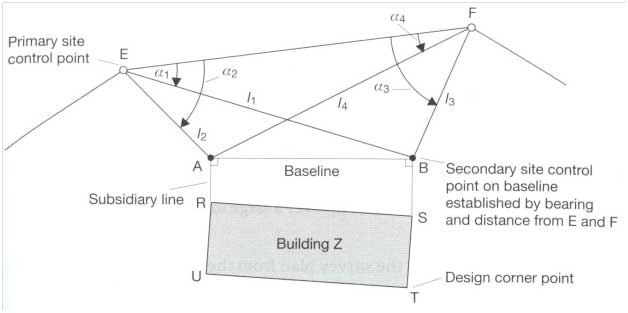
 In order that
design points on the works can be positioned at their correct levels, vertical
control points of known elevation relative to some specified vertical datum are
established. In practice, 20mm diameter steel bolts and 100mmlong,
with known reduce levels driven into existing steps, ledges, footpaths etc. may
serve as vertical controls.
In order that
design points on the works can be positioned at their correct levels, vertical
control points of known elevation relative to some specified vertical datum are
established. In practice, 20mm diameter steel bolts and 100mmlong,
with known reduce levels driven into existing steps, ledges, footpaths etc. may
serve as vertical controls.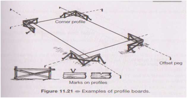
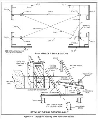
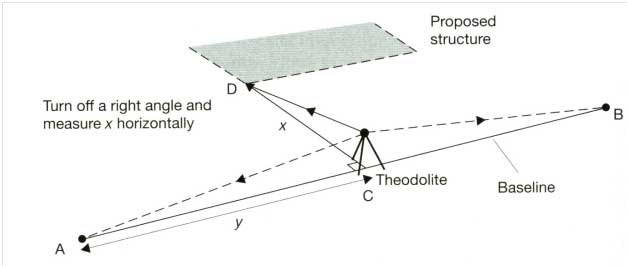
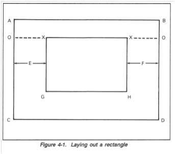 Suppose
we know the co-ordinates(x,y) of the points X with respect to point A then we
can locate it by measuring their x distance along line AB and y distance along
line AC and BD respectively to locate them. These two points can be joined to
make line XX. To locate point G and H, straight line are set out using 3-4-5
triangle rule and distance XG and XH which is known is marked on those lines.
After the four corners (X, X, G. and H) have been located, drive stakes at each
corner. Dimensions are determined accurately during each step.
Suppose
we know the co-ordinates(x,y) of the points X with respect to point A then we
can locate it by measuring their x distance along line AB and y distance along
line AC and BD respectively to locate them. These two points can be joined to
make line XX. To locate point G and H, straight line are set out using 3-4-5
triangle rule and distance XG and XH which is known is marked on those lines.
After the four corners (X, X, G. and H) have been located, drive stakes at each
corner. Dimensions are determined accurately during each step.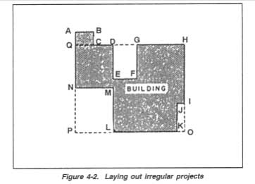 Where
the outline of the building is other than a rectangle, the procedure in
establishing each point is the same as defined for laying out a simple
rectangle. However, more points have to be positioned, and the final proving of
the work is more likely to disclose a small error. When the building is an
irregular shape, it is sensible to first lay out a large rectangle which will
includes the entire building or the greater part of it. This is shown in Figure
4-2 as HOPQ When this is established, the remaining portion of the layout will
consist of small rectangles, each of which can be laid out and shown
separately. These rectangles are shown as LMNP ABCQ, DEFG, and IJKO in Figure
Where
the outline of the building is other than a rectangle, the procedure in
establishing each point is the same as defined for laying out a simple
rectangle. However, more points have to be positioned, and the final proving of
the work is more likely to disclose a small error. When the building is an
irregular shape, it is sensible to first lay out a large rectangle which will
includes the entire building or the greater part of it. This is shown in Figure
4-2 as HOPQ When this is established, the remaining portion of the layout will
consist of small rectangles, each of which can be laid out and shown
separately. These rectangles are shown as LMNP ABCQ, DEFG, and IJKO in Figure