Experiment No.1
Object : To measure of the horizontal angle by a general method.
Apparatus: Theodolite with stand, ranging rods.
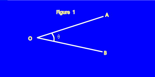
The direct or general method of measuring horizontal angle, consider
the fig. 1 suppose an angle AOB is to be measured. The following
procedure is adopted.
Procedure:
1. Set up the instrument at 0.
(It means that centering and leveling done perfectly) B
2. Keep the vertical circle to be left position. Fig. 1
3. By keeping the lower clamp is fixed. The upper clamp is loosened and by
turning the telescope clockwise, vernier A is set to 00 and vernier B to approximately at 180°.
4. The upper clamp is then tightened. Now by turning the upper tangent screw, verniers A and B are set to
exactly 0° and 180° by looking through the magnifying glass.
5. By keeping the upper clamp fixed, loosen the lower and the telescope is directed to the left hand object. ie. A.
6. The ranging rod A is bisected approximately by properly focusing the telescope and eliminating parallax.
7. Now the lower clamp is tightened and ranging rod A is accurately bisected.
8. By keeping the lower clamp fixed, the upper clamp is loosened.
9. The telescope is turned clockwise to approximately bisect the ranging rod at B by properly focusing the
telescope. The upper clamp is tightened and the ranging rod at B is bisected accurately by turning the upper
tangent screw.
10. The readings on vernier A and B are noted.
11. Vernier A gives the reading directly. But in case of vernier B, the angle is obtained by subtracting the initial reading from the final reading.
12. The readings are noted in tabular form as in table 5.1.
13. The face of the instrument is changed and the above procedure is followed.
14. The readings of the verniers are noted in the table.
15.The mean of the observations (i.e. face left and right) is the actual angle < AOB.
16. The two observations are taken to eliminate any possible error due to imperfect adjustment of the instrument.
Precautions:
1. If required, the plate bubble should be centered after sighting, using foot screws, but the foot screws should not be touched between the initial sighting and the final sighting of the line of sight.
2. Use rifle sights on the telescope for rough pointing before sighting through the telescope.
3. Make a reasonably close setting by hand when the clamp screw is still loose so that the tangent screw will not need to be turned through more than one to two revolutions.
4. Do not over-tighten the clamp screws.
5. Do not apply force for turning the screws.
6. The vertical hair of the diaphragm is important while measuring the horizontal angles. The vertical hair should bisect the signals as accurately as possible
NOTE:-MAKE THREE TABLE’S AND ATTACH IN YOUR FILES


No comments:
Post a Comment